Monday, 31 December 2018

MPPT SOLAR CHARGE CONTROLLER

NOTICE:
Please note that this design is not a student project, and no file(s) will be release on freebies
Phone/ Whatsapp/ Imo/ Telegram : +2348123206299
Email: acecct.18f4550@gmail.com
copyright @ T9 LEGENDARY RELIABILITY DESIGNS.

File A: (220 usd)
circuit diagram, proteus file, hex file with your company name , inductor calculation, capacitor calculation, mosfet calculation and setup video.

File B: (550 usd)
circuit diagram, proteus file, source code with compiler (Code written in Clang.), inductor calculation, capacitor calculation, mosfet calculation  and setup video.


Specification:
1.Based on MPPT algorithm
2. LED indication for the state of charge
3. 16x2 character LCD display for displaying voltages,current,power etc
4. Overvoltage / Lightning protection
5. Short Circuit and Over load protection
6.Serial port data monitor
7.Synchronous operation with high and low side MOSFETS for better buck converter efficiency
8.Dual high side MOSFETS arranged back to back to prevent current leakage in low light

TECHNICAL SPECIFICATIONS:
Battery voltage: 12vdc/24vdc/48vdc
Solar max. input voltage: 100vdc
Max. current : 60A

MPPT SOLAR CHARGE CONTROLLER

Well, The most advance solar charge controller available in the market is Maximum Power Point Tracking (MPPT).The MPPT controller is more sophisticated and more expensive.It has several advantages over the earlier charge controller.It is 30 to 40 % more efficient at low temperature.But making a MPPT charge controller is little bit complex in compare to PWM charge controller.It require some basic knowledge of power electronics.


What Is MPPT ?
The Maximum Power Point Tracker (MPPT) circuit is based around a synchronous buck converter circuit..It steps the higher solar panel voltage down to the charging voltage of the battery. The Arduino tries to maximize the watts input from the solar panel by controlling the duty cycle to keep the solar panel operating at its Maximum Power Point.

The Maximum Power Point Tracker (MPPT)  controller increase charge current by operating the PV module in a manner that allows the module to produce all the power it is capable of a conventional charge controller simply connects the module to the battery when the battery is discharged. When the 75W module in this example is connected directly to a battery charging at 12 volts its power production is artificially limited to about 53 watts. This wastes a whopping 22 watts or nearly 30% of the available power!

Patented MPPT technology used in this MPPT controller design operates in a very different fashion. The  MPPT controller continually calculates the modules maximum power voltage, in this case 17 volts. It then operates the module at its maximum power voltage to extract maximum power. The higher power extracted from the module is then provided to the battery in the form of increased charge current. In conditions where extra PV power is not available, Sigma MPPT controller will operate as a conventional controller with very low voltage drop.


The mosfet driver
A Mosfet driver allows a low current digital output signal from a Microcontroller to drive the gate of a Mosfet. A 5 volt digital signal can switch a high voltage mosfet using the driver.A MOSFET has a gate capacitance that you need to charge so that the MOSFET can turn on and discharge it to switch off,the more current you can provide to the gate the faster you switching on/off the mosfet, that is why you use a driver.
For this design I am using a IR2104 Half Bridge driver. The IC takes the incoming PWM signal from the micro controller, and then drives two outputs for a High and a Low Side MOSFET.

Input :
First we have to provide power to the gate driver.It is give on Vcc (pin-1) and its value is in between 10-20V as per data sheet.
The high frequency PWM signal from atmega ic goes to IN (pin-2) . The shut down control signal from the atmega ic is connected on SD ( pin 3).

Output :
The 2 output PWM signals are generated from HI and LO pin. This gives the user the opportunity to fine tune the dead-band switching of the MOSFETs.

Charge Pump Circuit :
The capacitor connected between VB and VS along with the diode form the charge pump.This circuit doubles the input voltage so the high switch can be driven on. However this bootstrap circuit only works when the MOSFETs are switching.


fig1.2:  


Some useful design tools

1. InductorRing program from Vladmir Denisenko (search google)


2. Power stage designer tool from Texas Instruments


3. American Wire Gauge Conductor Size Table


PCB, SIMULATION, HARDWARE AND SOLDERING:
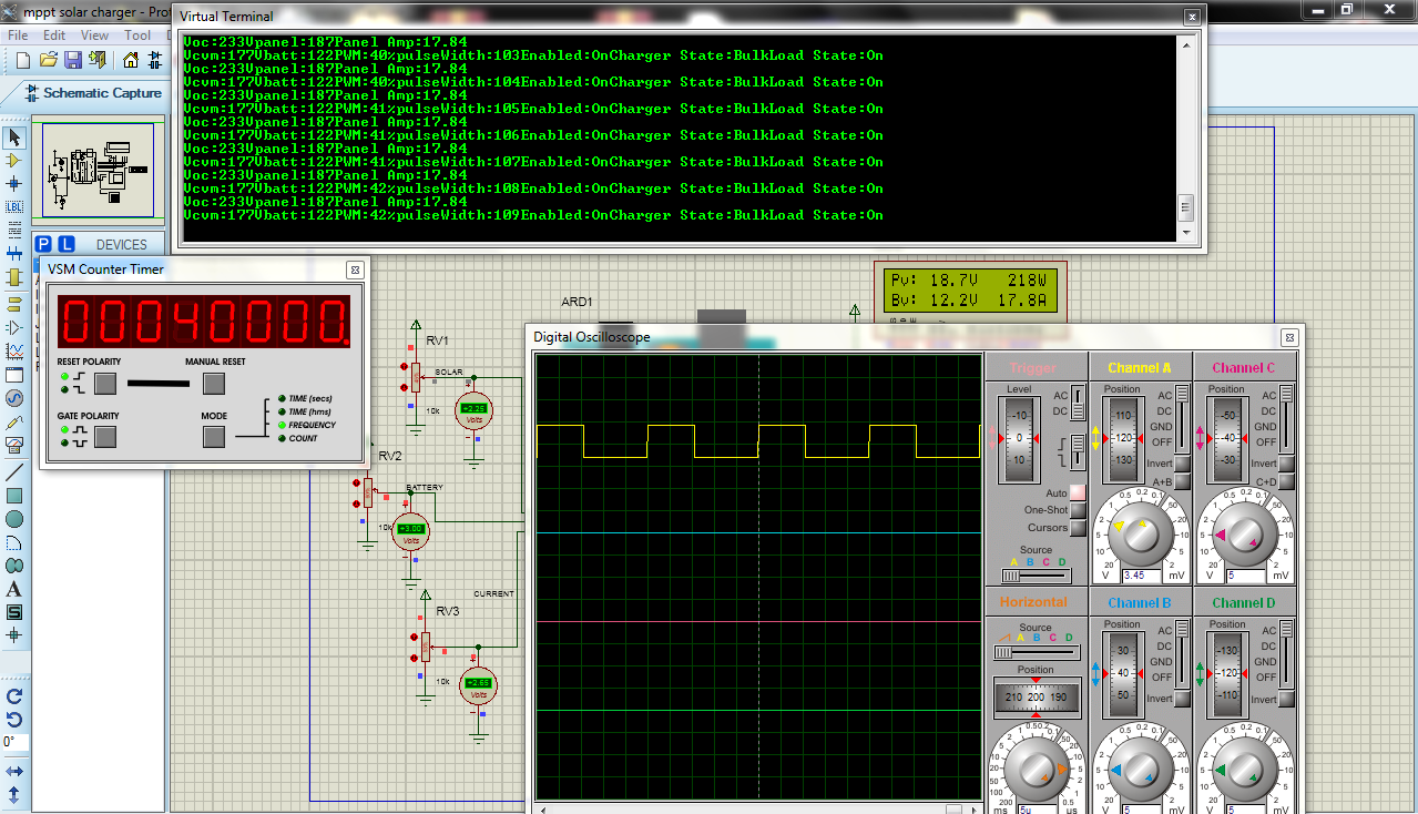

fig2.1: proteus simulation with 40khz mosfet sw..


fig2.2: printed pcb board with top sink printed


fig2.3: printed pcb board with bottom sink printed


fig2.4: Inductor design (22uH 20A)


fig2.5: printed pcb board with complete component for 12v design. 


fig2.6: printed pcb board with 12vdc fan


fig2.7: testing on 150watts solar panel to charge 40ah lifepo4 battery


fig2.8: testing on 150watts solar panel to charge 40ah lifepo4 battery


fig2.9: nice packaging is needed too..


Youtube video:  click here
https://www.youtube.com/watch?v=o4izARSjENg


Thursday, 14 June 2018

Proteus Professional 8.5

Proteus Professional 8.5


The new version of Proteus is more than three years of continuous development and includes improvements in every area of ​​the software suite. A major work on the structure of the application in conjunction with the introduction of a common database that enables a workflow much more smoothly for users while the new set of features saves time and effort in the project life cycle.


How to install

  • Unzip the .rar file.
  • Run the file Proteus Professional 8.5 – SP0 – DEMO.exeand follow the installation instructions.
  • During installation select the license locally, using the file License Key.lxk. A license manager window should appear. Use Browser for Key Fileto load the license and Installto install it.
  • Finally, run the file Update Proteus 8.5 SP0 DEMO to PRO.exeto unlock the demo version. In the address field, look for the folder where the Proteus has been installed, it is usually: C:\Program Files (x86)\Labcenter Electronics\Proteus 8 Professional.   
Click here to download

Thursday, 1 March 2018

Embedded system training Course - online


Embedded system
An embedded system is a computer system with a dedicated function within a larger mechanical or electrical system, often with real-time computing constraints. It is embedded as part of a complete device often including hardware and mechanical parts. sources: Wikipedia
 

Embedded system training Course Outline:
Embedded system introduction
Microcontroller system
Home made pcb design
Pic microcontroller family
Atmega microcontroller family
PIC basic professional programming
Atmega _ arduino programming
PIC microcontroller project (car park control system, RF wireless control, mini home
automation, traffic light control)
Atmega microcontroller project (rfid tag security door access control, automated texter,
xbee wireless control, finger print door access control)

FEE: ₦70,000 for full package
Phone/ Whatsapp/ Imo/ Telegram : +2348123206299
EMail: acecct.18f4550@gmail.com

Wednesday, 31 January 2018

Simple car tracker with ATmega328a

Simple car tracker with ATmega328a


Components needed:
1. ATmega328
2. Sim300 gsm module
3.  GY-GPS6MV2 gps module
4. Android smartphone
5. lcd 16x2
6. back_up battery


Here in this system we are using the GSM module for sending the coordinates of vehicle on mobile phone via message. GPS is sends the coordinates continuously in form of string. After reading this string using Arduino extract the required data from string and then sends it to mobile phone using GSM module via SMS. This information is called latitude and longitude. GPS used 3 or 4 satellite for tracking the location of any vehicle.


Circuit diagram


 Car tracker controller with Atmega328

Gsm testing


Gps module testing


 Command testing


 // here is the code...........
//......................................................................
#include<LiquidCrystal.h>
LiquidCrystal lcd(8,9,10,11,12,13);

#include <SoftwareSerial.h>
SoftwareSerial gps(7,6); // RX, TX

char c=0;

//String str="";
char str[70];
String gpsString="";

char *test="$GPGGA";

String latitude="No Range      ";
String longitude="No Range     ";

int temp=0,i;
boolean gps_status=0;

void setup()
{
  lcd.begin(16,2);
  Serial.begin(9600);
  gps.begin(9600);

  lcd.print("Vehicle_Tracking");
  lcd.setCursor(0,1);
  lcd.print("    System      ");
  delay(4000);
  gsm_init();
  lcd.clear();
  Serial.println("AT+CMGF=1");
  lcd.print("Pls Wait......");
  lcd.setCursor(0,1);
  lcd.print("SW TO SMS MODE");
  delay(2500);
  lcd.clear();
  lcd.print("GPS Initializing");
  lcd.setCursor(0,1);
  lcd.print("  No GPS Range  ");
  get_gps();
  delay(2500);
  lcd.clear();
  lcd.print("GPS Range Found");
  lcd.setCursor(0,1);
  lcd.print("GPS is Ready");
  delay(2500);
  lcd.clear();
  lcd.print("System Ready");
    lcd.setCursor(0,1);
  lcd.print("Vehicle secured");
Serial.println("AT+CMGD=1"); // DELETE READ1
  delay(3000);
   digitalWrite(2, LOW);   // turn the LED on (HIGH is the voltage level)
  delay(10);              // wait for a second
  digitalWrite(3, LOW);
  delay(10); 
}


void loop()
{
  lcd.setCursor(0,1);
  lcd.print("waiting 4 command");
  Serial.println("AT+CMGR=1");
  while (Serial.available()) {
    if (Serial.find("TRACK VEHICLE")) {
    digitalWrite(2, HIGH);
    get_gps();
    Serial.println("AT+CMGD=1"); // DELETE READ1
    tracking();
    }
   
    if (Serial.find("OFF ALARM")) {
  digitalWrite(2, LOW);   // turn the LED on (HIGH is the voltage level)
  delay(10);             
  digitalWrite(3, LOW);
  delay(10); 
    Serial.println("AT+CMGD=1"); // DELETE READ1
    tracking();
    }
  }


void gpsEvent()
{
  gpsString="";
  while(1)
  {
   while (gps.available()>0)            //checking serial data from GPS
   {
    char inChar = (char)gps.read();
     gpsString+= inChar;                    //store data from GPS into gpsString
     i++;
     if (i < 7)                     
     {
      if(gpsString[i-1] != test[i-1])         //checking for $GPGGA sentence
      {
        i=0;
        gpsString="";
      }
     }
    if(inChar=='\r')
    {
     if(i>65)
     {
       gps_status=1;
       break;
     }
     else
     {
       i=0;
     }
    }
  }
   if(gps_status)
    break;
  }
}

void gsm_init()
{
  lcd.clear();
  lcd.print("Finding Module..");
  boolean at_flag=1;
  while(at_flag)
  {
    Serial.println("AT");
    while(Serial.available()>0)
    {
      if(Serial.find("OK"))
      at_flag=0;
    }
   
    delay(1000);
  }

  lcd.clear();
  lcd.print("Module Connected..");
  delay(1000);
  lcd.clear();
  lcd.print("Disabling ECHO");
  boolean echo_flag=1;
  while(echo_flag)
  {
    Serial.println("ATE0");
    while(Serial.available()>0)
    {
      if(Serial.find("OK"))
      echo_flag=0;
    }
    delay(1000);
  }

  lcd.clear();
  lcd.print("Echo OFF");
  delay(1000);
  lcd.clear();
  lcd.print("Finding Network..");
  boolean net_flag=1;
  while(net_flag)
  {
    Serial.println("AT+CPIN?");
    while(Serial.available()>0)
    {
      if(Serial.find("+CPIN: READY"))
      net_flag=0;
    }
    delay(1000);
  }
  lcd.clear();
  lcd.print("Network Found..");
  delay(1000);
  lcd.clear();
}

void get_gps()
{
   gps_status=0;
   int x=0;
   while(gps_status==0)
   {
    gpsEvent();
    int str_lenth=i;
    latitude="";
    longitude="";
    int comma=0;
    while(x<str_lenth)
    {
      if(gpsString[x]==',')
      comma++;
      if(comma==2)        //extract latitude from string
      latitude+=gpsString[x+1];    
      else if(comma==4)        //extract longitude from string
      longitude+=gpsString[x+1];
      x++;
    }
    int l1=latitude.length();
    latitude[l1-1]=' ';
    l1=longitude.length();
    longitude[l1-1]=' ';
    lcd.clear();
    lcd.print("Lat:");
    lcd.print(latitude);
    lcd.setCursor(0,1);
    lcd.print("Long:");
    lcd.print(longitude);
    i=0;x=0;
    str_lenth=0;
    delay(2000);
   }
}

void init_sms()
{
  Serial.write("AT+CMGF=1\r\n");
  delay(1000);
  Serial.write("AT+CMGS=\"+2347037557572\"\r\n");   // use your 10 digit cell no. here
  delay(1000);
}

void send_data(String message)
{
  Serial.println(message);
  delay(200);
}

void send_sms()
{
  Serial.write((char)26);
}

void lcd_status()
{
  lcd.clear();
  lcd.print("Message Sent");
  delay(2000);
  lcd.clear();
  lcd.print("System Ready");
  return;
}

void tracking()
{
  digitalWrite(3, HIGH);   // turn the LED on (HIGH is the voltage level)
  delay(10);              // wait for a second
  digitalWrite(2, LOW);
    init_sms();
    send_data("Vehicle Tracking Alert:");
    send_data("Your Vehicle Current Location is:");
    Serial.print("Latitude:");
    send_data(latitude);
    Serial.print("Longitude:");
    send_data(longitude);
    send_data("Please take some action soon..\nThankyou");
    send_sms();
    delay(2000);
    lcd_status();
     Serial.println("AT+CMGD=1"); // DELETE READ1
}
// ending

 If you have any question, feel free to comment on this post.... acecct.18f4550@gmail.com OR whatsapp me on :  +2348123206299
 
 
Watch Youtube Video: 


Saturday, 30 July 2016

PURE SINEWAVE WITH LCD USING DSPIC30F2010

DSP30F2010 SINEWAVE INVERTER

TECHNICAL SPECIFICATIONS:

VOLTAGE LIMITS (INVERTER MODE) :
    Mains A.C. Lower Voltage Limit :110+ 5V Lower Recovery Voltage :120+ 5V
    Mains A.C. Higher Voltage Limit : 275+ 5V Higher Recovery Voltage : 265+ 5V
    Output Voltage in Inverter Mode : 210V+5%

VOLTAGE LIMITS (UPS MODE) :
    Mains A.C. Lower Voltage Limit :180+ 5V Lower Recovery Voltage : 190+ 5V
    Mains A.C. Higher Voltage Limit : 255+ 5V Higher Recovery Voltage : 245+ 5V

 Output Frequency :
   Main Output Frequency : Same as Input Inverter, Output Frequency : 50.0+0.3Hz

CHARGER:
   DSP controlled CC/CV Charger with Soft Start

TECHNOLOGY :
    Processor: DSP
    Conversion: Full H bridge
    Switching: 20 Khz Modulation
    Charging: Dynamic five stage charger to decrease charging time and increase battery life

PROTECTIONS:
Battery voltage
Inverter output voltage
Percentage of load
Mains voltage
Changer on/off
Solar charging /mains charging
Inverter standby on/off
UPS mode / inverter mode
Phase input output reverse : whether mains is connected to inverter output
Neutral and phase reverse : whether neutral and phase is connected reverse
Overload
Short circuit
Overload trip
Heavy load trip
Short circuit trip


Fig 1... dsp empty panel


Fig 2... testing o/put frequency


Fig 3... testing and loading


Fig 4... old dsp empty panel 


Fig 5... assembling


Fig 6... 3500va 48v dsp design

 
Fig 7... 3.5kva 48v dsp on calibration


Fig 8... complete dsp inverter 2  


Fig 9... 2400va dsp inverter  


dsp inverter card video link


To purchase new dsp green inverter panel (empty & complete)
Call- 08123206299, 08134573457

 If you have any question, feel free to comment on this post.... acecct.18f4550@gmail.com OR whatsapp me on :  +2348123206299
 
 DSP30F2010 SINEWAVE
Configuration video (30mins): https://www.youtube.com/watch?v=RijSafGgB1c

HEART BEAT PROJECT USING ATMEGA328

HEART BEAT PROJECT USING ATMEGA328P


PROJECT DESCRIPTION:

Heart rate, body temperature and blood pressure monitoring are very important parameters of human body. Doctors use various kind of medical apparatus like thermometer for checking fever or body temperature, BP monitor for blood pressure measurement and heart rate monitor for heart rate measurement.  Here we have used a heartbeat sensor module which senses the heartbeat by the pulse in ear, Heart rate ear clip kit contain a ear clip and a receiver module. The heart rate measure kit can be used to monitor heart rate of patient and athlete. The result can be displayed on a screen via the serial port and can be saved for analysis. The entire system has a high sensitivity, low power consumption and is very portable.

This simple project will allow you to visualize your heart rate result  through a  Bluetooth connection with an  android moblie phone using hc-06  Bluetooth module

COMPONENT:


  1. Atmega328p
  2. Heart rate ear clip
  3. LCD 16X 2
  4. Bluetooth module


Fig 1...  Heart rate ear clip


Fig 2...  HC-06 Bluetooth module


Fig 3... PCB design 


Fig 4... First test


Fig 5... Testing 1


Fig 6... Testing 2


Fig 7... Testing 3 

Here is the code:

//ACE TECHNOLOGY '15
//HEART BEAT AND BLUETOOTH RECIEVER
//AKINSINMIDE IMOLEAYO
//ATMEGA328
//ACECCT.BLOGSPOT.COM

// include the library code:
#include <LiquidCrystal.h>

// initialize the library with the numbers of the interface pins
LiquidCrystal lcd(5,6,7,8,9,10);

#include <SoftwareSerial.h>// import the serial library

SoftwareSerial Genotronex(12, 11); // RX, TX
int ledpin=13; // led on D13 will show blink on / off
int BluetoothData; // the data given from Computer

#define LED 4 //indicator, Grove - LED is connected with D4 of Arduino
boolean led_state = LOW;//state of LED, each time an external interrupt
                //will change the state of LED
unsigned char counter;
unsigned long temp[21];
unsigned long sub;
bool data_effect=true;
unsigned int heart_rate;//the measurement result of heart rate

const int max_heartpluse_duty = 2000;//you can change it follow your system's request.
            //2000 meams 2 seconds. System return error
            //if the duty overtrip 2 second.
void setup()
{
    Genotronex.begin(9600);
  Genotronex.println(" HEART RATE MONITORING PROJECT ");
  delay (500);
  Genotronex.println(" BLUETOOTH DEVICE CONNECTED... "); 
  pinMode(ledpin,OUTPUT);
 delay (1000); // delay for lcd to boot up
    // initialize LCD and set up the number of columns and rows:
  lcd.begin(16, 2);
  delay (1000);
 
  lcd.clear();
  lcd.setCursor(0,0);
  lcd.print("   HEART RATE   ");
  lcd.setCursor(0,1);
  lcd.print("    MONITOR     ");
  delay (2500);
   Genotronex.println(" HEART RATE MONITORING PROJECT ");

  pinMode(LED, OUTPUT);
  Serial.begin(9600);
  arrayInit();
    lcd.clear();
  lcd.setCursor(0,0);
  lcd.print("   HEART RATE   ");
  lcd.setCursor(0,1);
  lcd.print(" TEST BEGIN.... ");
 
   Genotronex.println(" SCANNING PULSE BEGIN..... ");

  delay (2500);
  attachInterrupt(0, interrupt, RISING);//set interrupt 0,digital port 2


}
void loop()
{
  digitalWrite(LED, led_state);//Update the state of the indicator
}
/*Function: calculate the heart rate*/
void sum()
{
 if(data_effect)
    {
      heart_rate=1200000/(temp[20]-temp[0]);//60*20*1000/20_total_time
          lcd.clear();
    lcd.setCursor(0,1);
    lcd.print("Heartrate_is: ");
    lcd.print(heart_rate);
   Genotronex.println(" YOUR HEART_RATE IS: ");
   Genotronex.println(heart_rate);

   delay (1000);
    }
   data_effect=1;//sign bit
}
/*Function: Interrupt service routine.Get the sigal from the external interrupt*/
void interrupt()
{
    temp[counter]=millis();
  Serial.println(counter,DEC);    Serial.println(temp[counter]);
    digitalWrite(13, HIGH);
        lcd.clear();
  lcd.setCursor(0,0);
  lcd.print(" SCANNING ......");
      lcd.setCursor(0,1);
    lcd.print("Heartrate_is: ");
    lcd.print(heart_rate);
  delay (50);
 digitalWrite(13, LOW );
    switch(counter)
  {

   case 0:
      sub=temp[counter]-temp[20];
      Serial.println(sub);
      break;
    default:
      sub=temp[counter]-temp[counter-1];
      Serial.println(sub);
      break;
  }
    if(sub>max_heartpluse_duty)//set 2 seconds as max heart pluse duty
  {
    data_effect=0;//sign bit
    counter=0;
       Genotronex.println(" HEART BEAT SENSOR IS NOT WELL CONNECTED.. ");
    lcd.clear();
  lcd.setCursor(0,0);
  lcd.print("   HEART RATE   ");
  lcd.setCursor(0,1);
  lcd.print("  READS  ERROR  ");
  delay (2500);
arrayInit();
  }
    if (counter==20&&data_effect)
    {
    counter=0;
    sum();
    }
    else if(counter!=20&&data_effect)
    counter++;
    else
    {
    counter=0;
    data_effect=1;
    }
   
}
/*Function: Initialization for the array(temp)*/
void arrayInit()
{
  for(unsigned char i=0;i < 20;i ++)
  {
    temp[i]=0;
  }
  temp[20]=millis();
}


 If you have any question, feel free to comment on this post.... acecct.18f4550@gmail.com OR whatsapp me on :  +2348123206299
 
Heart rate project complete file can be downloaded  in the link below:
Link: Pcb design and code

Thursday, 28 July 2016

SOLAR CHARGE CONTROLLER USING PIC16F876A (ZERO DROP)

ZERO DROP SOLAR CHARGE CONTROLLER


PROJECT DESCRIPTION:

This circuit degisn is called ‘zero drop solar charger’ because it doesn't have any diode drop of 0.7v. This is a mosfet based design which has very negligible voltage drop of  0.05v or less which means the loss is very less, ideal for solar applications.
       Since the drop is less, the losses are negligible so the efficiency achieved is > 99.5%

      In this the two n channel mosfets are connected in such a way that their sources become common and the drains will be connected to the negatives of battery and solar panel respectively and the gate will be triggered by the microcontroller (pic16f876a).

     The positives of solar panel and battery will be joined directly and the circuit was powered from that joint.

      When the solar power was present the circuit gets activated and micro-controller will pumps the signals that to trigger the gate of mosfet, when the gate was triggered the negative voltage will flow through the mosfet and then the battery will be charged through solar panel.
Specification: 
Voltage         12v - 96v
Current        10A - 60A
Efficiency    > 99.6%
Protection against : Panel reverse
                                   Battery reverse
                                   Battery Overcharge ( full charge cut - off level is settable )
Charger monitor  - 16 x 2 lcd display
Other feature - Opto - Coupler output for Charging signal to external circuits (like inverters)


fig 1... First design


fig 2... Connection and configuration


fig 3...Model design 


 fig 4... 12V - 48V design 


fig 5... configuration 1


fig 6... configuration 2


fig 7... configuration 3 


To purchase ZERO DROP SOLAR CHARGE CONTROLLER (empty & complete) 
Lagos (nigeria): Call- 09020322481
Akure (nigeria): Call- 08123206299
Email :  acecct.18f4550@gmail.com 

 If you have any question, feel free to comment on this post.
 
Zero drop charging complete file can be downloaded  in the link below:


Featured post

PURE SINE WAVE INVERTER WITH LED AND LCD

The inverter PCB is easy to assemble by following the label of the components to be inserted. The choice of the voltage to be used to power ...