Thursday, 25 June 2015

PICKIT 2 CLONE PROGRAMMER

PICKIT 2 CLONE PROGRAMMER

PROJECT DESCRIPTION:

This is my PICkit 2 clone design. Its based on a simplified version of the Microchip PICkit 2 schematic and only supports 5v parts. It works with all the Microchip software including MPLAB, MPLABX,the PICkit 2 GUI Programming software and the PICkit 2 command line software.


FIG1: CIRCUIT DIAGRAM


FIG2: 3D PREVIEW

FIG3: PCB  VIEW1


FIG4: PCB  VIEW2


FIG5: PCB  VIEW3


FIG6: TESTING1


FIG6: 28 PIN uC configration


FIG6: 18 PIN uC configration


FIG6: 8 PIN uC configration 


FIG6: 8 NEW PICKIT2 WITH DSP SOCKET


To purchase PICKIT 2 CLONE PROGRAMMER (empty & complete) 
Lagos (nigeria): Call- 09020322481
Akure (nigeria): Call- 08123206299
Email :  acecct.18f4550@gmail.com 

 If you have any question, feel free to comment on this post.... acecct.18f4550@gmail.com OR whatsapp me on :  +2348123206299

PICKIT 2 CLONE PROGRAMMER COMPLETE FILE:  https://www.datafilehost.com/d/b06ac5ef

Sunday, 21 June 2015

PCB LAMINATOR CONTROLLER, CODE AND PCB PRINTING

PCB ASSISTANT LAMINATOR CONTROL: 

To make smart looking PCB's, all you need is: A computer, a laser printer, copper clad board, etchant, A3/A4 laminating machine and some  glossy photo paper. You can buy special film for making PCB's, but I have found that the glossy paper gives better results. I use photo quality glossy paper for inkjet printers.

I got an  A3/A4 laminating machine for about $40(N 8000) in the computer store last week, for my sine wave mother board production, and i needed to produce a total sum of 50 pcs control boards for a new consumer of mine... then, i got tried of the forward and the reverse of a single control board for about 25 times  to get it done... well, i was able to press about 12pcs  in 2 days... then i taught of making a pcb  assistant laminator control  with a lcd display...

Use a laser printer to print the image on the glossy side of the photo paper. Clean the copper clad board with steel wool or very fine wet sandpaper. Dry the board thoroughly. Make sure that the board is clean and free from fingerprints. Place the photo paper face down on the copper clad board. Use masking tape to hold the paper in position. Don't use vinyl tape. Place the board on a flat surface. You will be using a very hot iron, so don't use the dining room table. I use the back of an old telephone directory. Use a hot clothes iron to transfer the track pattern from the paper to the copper board. Don't be afraid to use lots of heat and pressure. Allow the board to cool. Don't be tempted to lift the paper. Put the board in a container full of warm soapy water. After about twenty minutes the paper will begin to dissolve and disintegrate. Carefully remove the paper from the copper board. Rinse under a cold tap to remove paper residue. You may need to touch up any broken tracks with an etch resist pen. I use a fine Staedtler laundry marker.

VIDEO: =https://youtu.be/cbb-fya8asU


The featuring M.C.U is the pic16f876a:


Circuit


Simulation test


Control board


Pcb design 1


Pcb design 2


Old design


New design 1


New design 2


New design 3


New design 4

Code written in picbasic pro

'****************************************************************
'*  Name    : LAMINATING MACHINE.BAS                            *
'*  Author  : AKINSINMIDE IMOLEAYO                              *
'*  Notice  : Copyright (c) 2015 [select VIEW...EDITOR OPTIONS] *
'*          : All Rights Reserved                               *
'*  Date    : 5/31/2015                                         *
'*  Version : 1.0                                               *
'*  Notes   :                                                   *
'*          :                                                   *
'****************************************************************

'F876A

Define   OSC 4          ' 4MHz crystal used

' Define ADCIN parameters
Define ADC_BITS     10    ' Set number of bits in result
Define ADC_CLOCK    3     ' Set clock source (3=rc)
Define ADC_SAMPLEUS 50   ' Set sampling time in uS   

'--------------[LCD DEFINES]----------------------
DEFINE LCD_DREG PORTC ' LCD Data bits on PORTC
DEFINE LCD_DBIT 4 ' PORTB starting address
DEFINE LCD_RSREG PORTC ' LCD RS bit on PORTC
DEFINE LCD_RSBIT 2 ' LCD RS bit address
DEFINE LCD_EREG PORTC ' LCD E bit on PORTC
DEFINE LCD_EBIT 3' LCD E bit address
DEFINE LCD_BITS 4 ' LCD in 4-bit mode
DEFINE LCD_LINES 2

'-------------[PORT INITIALIZATION]-----------------
TRISA = 001111      ' Set PORTA as  INPUT AND OUTPUT
ADCON1 = %10000010  ' Set PORTA analog and right justify result
PORTB = 000000     'set PORTB as output
TRISB = 001111    'set TRISB as both input and output

'VARIABLE ------------------------------
A VAR WORD : A = 0
B VAR WORD : B = 0
 LED_FLASH VAR BYTE
 BT VAR WORD : BT = 0
 BT1 VAR WORD : BT1 = 0
 BT2 VAR WORD : BT2 = 0
 UNIT VAR WORD [40] : UNIT = 0
 L_UNIT VAR WORD : L_UNIT = 0
 W_UNIT VAR WORD : W_UNIT = 0
 R_UNIT VAR WORD : R_UNIT = 0
 RUN_UNIT VAR WORD :  RUN_UNIT = 0
 COUNTEXIT VAR WORD : COUNTEXIT = 0
 COUNTOK VAR WORD : COUNTOK = 0
 COUNTRUN VAR WORD : COUNTRUN = 0
 COUNT_EXIT VAR WORD : COUNT_EXIT = 0
 L0 var word : L0 = 0

'----------- [PORT B] -------------
BUZZER VAR PORTB.7
FORWARD VAR PORTB.6
BACKWARD VAR PORTB.5
ON_OFF VAR PORTB.4
OK_KEY VAR PORTB.3
EXIT_KEY VAR PORTB.2
UP_KEY VAR PORTB.1
DOWN_KEY VAR PORTB.0

'----------- [PORT C] -------------
WORKING_LED VAR PORTC.0
FINISHED VAR PORTC.1
BUZZ_DELAY CON 120

'---------[LCD INITIALIZATION]-----------
LCDOUT $FE,1 ' CLEAR SCREEN
LCDOUT $FE,2
PAUSE 1000          ' Wait 1 second

LOADING:
'FOR LED_FLASH = 0 TO 5
HIGH WORKING_LED : PAUSE 600
LOW WORKING_LED : PAUSE 300
'NEXT LED_FLASH
HIGH BUZZER :PAUSE BUZZ_DELAY :LOW BUZZER  :PAUSE 200
HIGH BUZZER :PAUSE BUZZ_DELAY :LOW BUZZER  :PAUSE 2

'---------------[ PROGRAM START HERE ]--------------------
MAIN: pause 10
high  ON_OFF
        LCDOUT $FE,1 ' CLEAR SCREEN
          pause 200 
LCDOUT "*****************"
LCDOUT $FE, $C0 : LCDOUT "|ACE TECHNOLOGY|" : PAUSE 2000 : LCDOUT $FE,1
LCDOUT " LAMINATING PCB "
LCDOUT $FE, $C0 : LCDOUT " PRO. ASSISTANT " : PAUSE 2000 : LCDOUT $FE,1
' ::::::::::::::::::::::::::::::::::::::::::::::::::::::::

MEASURE:
LCDOUT $FE,1 ' CLEAR SCREEN
PAUSE 2
LOW BACKWARD
PAUSE 120
LCDOUT "PLEASE ENTER PCB"
LOW FINISHED : low WORKING_LED  : HIGH FORWARD

GET_LENGTH:
pause 50 : GOSUB GET_KEY
L_UNIT = UNIT
LCDOUT $FE, $C0 : LCDOUT "LENGTH(S): " , DEC2 UNIT ," CM" : PAUSE 100
IF OK_KEY = 0 THEN
HIGH BUZZER :PAUSE BUZZ_DELAY :LOW BUZZER  :PAUSE 2
GOTO GET_WIDTH1
ENDIF
GOTO GET_LENGTH

GET_WIDTH1: PAUSE 2
UNIT = 0
GET_WIDTH:  
pause 50 : GOSUB GET_KEY
W_UNIT = UNIT
LCDOUT $FE, $C0 : LCDOUT "WIDTH(S) : " , DEC2 UNIT ," CM" : PAUSE 100
IF OK_KEY = 0 THEN
HIGH BUZZER :PAUSE BUZZ_DELAY :LOW BUZZER  :PAUSE 2
GOTO START1
ENDIF
GOTO GET_WIDTH

GET_KEY: 
PAUSE 50

IF UP_KEY = 0 THEN
HIGH BUZZER :PAUSE BUZZ_DELAY :LOW BUZZER  :PAUSE 2
UNIT = UNIT + 1
IF UNIT => 40 THEN UNIT = 40          'maximun no of times
ENDIF

PAUSE 50

IF DOWN_KEY = 0 THEN
HIGH BUZZER :PAUSE BUZZ_DELAY :LOW BUZZER  :PAUSE 2
IF UNIT =< 0 THEN
UNIT = 0
GOTO GET_KEY
ENDIF
UNIT = UNIT - 1
ENDIF

PAUSE 50

IF EXIT_KEY = 0 THEN
COUNT_EXIT = COUNT_EXIT + 1
IF COUNT_EXIT = 2 THEN
HIGH BUZZER :PAUSE BUZZ_DELAY :LOW BUZZER  :PAUSE 10
GOTO REMOVE
ENDIF
 ENDIF
RETURN


START1:
low FORWARD
LOW FINISHED : low WORKING_LED
LCDOUT $FE,1 ' CLEAR SCREEN

START:
PAUSE 2
LCDOUT "LENGTH(S): " , DEC2 L_UNIT ," CM"
LCDOUT $FE, $C0 : LCDOUT "WIDTH(S) : " , DEC2 W_UNIT ," CM" : PAUSE 1200
LCDOUT $FE,1 ' CLEAR SCREEN

FOR COUNTOK = 0 TO 10
LCDOUT "    PRESS OK    "
LCDOUT $FE, $C0 : LCDOUT "  TO  CONTINUE  ": PAUSE 120
IF OK_KEY = 0 THEN
HIGH BUZZER :PAUSE BUZZ_DELAY :LOW BUZZER  :PAUSE 3000
GOTO RUN
ENDIF
NEXT COUNTOK 
LCDOUT $FE,1 ' CLEAR SCREEN

FOR COUNTEXIT = 0 TO 10
LCDOUT "   PRESS EXIT   "
LCDOUT $FE, $C0 : LCDOUT "   TO  CANCEL   ": PAUSE 120
IF EXIT_KEY = 0 THEN
HIGH BUZZER :PAUSE BUZZ_DELAY :LOW BUZZER  :PAUSE 10
GOTO MEASURE
ENDIF
NEXT COUNTEXIT
LCDOUT $FE,1 ' CLEAR SCREEN

GOTO START

RUN:
LCDOUT $FE,1 ' CLEAR SCREEN
PAUSE 2  : UNIT = 0
LCDOUT "  PRESS OK !!!  "

GET_RUN:
pause 10 : GOSUB GET_KEY
LCDOUT $FE, $C0 : LCDOUT "COUNT: " , DEC2 UNIT ," TIMES"
IF OK_KEY = 0 THEN              
RUN_UNIT = UNIT
HIGH BUZZER :PAUSE BUZZ_DELAY :LOW BUZZER  :PAUSE 2
LCDOUT $FE,1 ' CLEAR SCREEN
GOTO LAMINATE
ENDIF
GOTO GET_RUN

LAMINATE :             ' laminating starts here
LOW FINISHED : high WORKING_LED  : LOW FORWARD
PAUSE 1500
LCDOUT $FE,1 ' CLEAR SCREEN
IF RUN_UNIT < 1 THEN GOTO DONE
LCDOUT "<<< WORKING. >>>"
LOW FINISHED : HIGH WORKING_LED
HIGH BUZZER :PAUSE BUZZ_DELAY :LOW BUZZER  :PAUSE 3000
HIGH FORWARD :  PAUSE 4000
HIGH BUZZER :PAUSE BUZZ_DELAY :LOW BUZZER  :PAUSE 2
LOW FORWARD : PAUSE 4000

'|||||||||||||||||||||||||||||||||||||||||||||||||
'    CALCULATE  MOVEMENT
L_UNIT = L_UNIT - 1
A = 1580 * L_UNIT
B = 1000
'||||||||||||||||||||||||||||||||||||||||||||||||

RUN_LAMINATE:

FOR COUNTRUN = 1 TO RUN_UNIT
LCDOUT "<<< WORKING. >>>"
LCDOUT $FE, $C0 : LCDOUT "COUNT ON : " , DEC2 COUNTRUN,"/",dec2 RUN_UNIT
IF EXIT_KEY = 0 THEN
HIGH BUZZER :PAUSE BUZZ_DELAY :LOW BUZZER  :PAUSE 2
LCDOUT $FE,1 ' CLEAR SCREEN                        
UNIT = 0
L_UNIT = 0
W_UNIT = 0
R_UNIT = 0
LCDOUT $FE, $C0 : LCDOUT " TASK CANCELLED " : PAUSE 2500
GOTO MEASURE
ENDIF

MOVE_FORWARD:                     
HIGH FORWARD : PAUSE A
LOW FORWARD  : PAUSE B

MOVE_BACKWARD:
HIGH BACKWARD : PAUSE A
LOW BACKWARD  : PAUSE B

LCDOUT $FE,1 ' CLEAR SCREEN
pause 1000
NEXT COUNTRUN

REMOVE:
L0 = 0
LOW FINISHED : high WORKING_LED  : LOW FORWARD
PAUSE 800
LCDOUT $FE,1 ' CLEAR SCREEN
PAUSE 200
HIGH BACKWARD
LCDOUT " PLEASE WAIT !!!"
LCDOUT $FE, $C0 : LCDOUT " EJECTING BOARD "
    for L0 = 0 to 12  ' BLINK  AND ROLL BACK DELAY
        lcdout $fe,$8
        pause 450
        lcdout $fe,$c
        pause 500
     next L0
       LOW BACKWARD
       pause 500
COUNT_EXIT = 0    :L0 = 0
COUNTOK = 0  : COUNTEXIT = 0
LCDOUT $FE,1 ' CLEAR SCREEN


DONE:
HIGH BUZZER : PAUSE BUZZ_DELAY : LOW BUZZER  :PAUSE 300
HIGH FINISHED : LOW WORKING_LED : low FORWARD
'LCDOUT "  PRESS EXIT!!! "
LCDOUT " TASK COMPLETED "
HIGH BACKWARD

FOR COUNTOK = 0 TO 10
LCDOUT $FE, $C0 : LCDOUT " <<OK>> TO REDO ": PAUSE 120
IF OK_KEY = 0 THEN
HIGH BUZZER :PAUSE BUZZ_DELAY :LOW BUZZER  :PAUSE 1200
LOW BACKWARD
PAUSE 1000
LOW FORWARD
PAUSE 2000
L_UNIT = L_UNIT + 1
GOTO LAMINATE        ' LAMINATED AGAIN
ENDIF
NEXT COUNTOK 

FOR COUNTEXIT = 0 TO 10
LCDOUT $FE, $C0 : LCDOUT "<EXIT> TO CANCEL": PAUSE 120
IF EXIT_KEY = 0 THEN
HIGH BUZZER :PAUSE BUZZ_DELAY :LOW BUZZER  :PAUSE 1200
LOW BACKWARD
UNIT = 0
L_UNIT = 0
W_UNIT = 0
R_UNIT = 0
PAUSE 1000
LOW FINISHED : low WORKING_LED  : HIGH FORWARD   : PAUSE 1000
LCDOUT $FE,1 ' CLEAR SCREEN
PAUSE 300 : GOTO MEASURE
ENDIF
NEXT COUNTEXIT 

GOTO DONE

END


CODE: https://www.dropbox.com/s/ewoa62jzrqusc7a/laminate%20code.txt?dl=0

HEX: https://onedrive.live.com/redir?resid=7B2431F2BDE45654!110&authkey=!AMetcTYhV7fHyUw&ithint=file%2cHEX

PCB:  https://onedrive.live.com/redir?resid=7B2431F2BDE45654!108&authkey=!AByhjoC4T7mEsf4&ithint=file%2cpdf


Sunday, 15 March 2015

SOLAR PWM CHARGING AND TRACKING SYSTEM

Introduction    
 The PV applications could be grouped according to the scheme of interaction with utility  grid: grid connected, stand alone, and hybrid. PV systems consist of a PV generator (cell, module, and array), energy storage devices (such as batteries), AC and DC consumers and elements for power conditioning. The most common method uses the PV cells in the grid network. However, to understand the performance and to maximize the efficiency of the irradiation of the PV cells, the standalone PV cells have spurred some interest, especially, in the area of the solar tracker system.
      Over the years, test and researchers had proven that development of smart solar tracker maximizes the energy generation. In this competitive world of advanced scientific discoveries, the introductions of automated systems improve existing power generation methods. Before the introduction of solar tracking methods, fixed solar panels were positioned within a reasonable tilted direction based on the location. The tilt angle depending on whether a slight winter or summer bias is preferred in the system. The PV systems would face “true north” in the northern hemisphere and “true south” in the southern hemisphere. Solar tracking is best achieved when the tilt angle of the tracking PV systems is synchronized with the seasonal changes of the sun’s altitude. Several methods of sun tracking systems have been surveyed and evaluated to keep the PV cells perpendicular to the sun beam. An ideal tracker would allow the PV cells to point towards the sun, compensating for both changes in the altitude angle of the sun (throughout the day), latitudinal offset of the sun (during seasonal changes) and changes in azimuth angle. In the light of this, two main types of sun trackers exist: passive (mechanical) and active (electrical) trackers

       One class of the passive solar trackers is the fixed solar panel. It is placed horizontally on
the fixed ground and face upwards to the sky. But most of the passive solar trackers are based on manual adjustment of the panel, thermal expansion of a shape memory alloy or two bimetallic strips made of aluminum and steel. Usually this kind of tracker is composed of a couple of actuators working against each other, which are, by equal illumination, balanced. By differential illumination of actuators, unbalanced forces are used for orientation of the apparatus in such direction where equal illumination of actuators and balance of forces is restored.
       Another passive tracking technology is based on the mass imbalance between both ends of the panel. This kind of trackers does not use any kind of electronic control or motor. Two identical cylindrical tubes are filled with a fluid under partial pressure. The sun heats the fluid causing evaporation and transfer from one cylinder to another, which creates the mass imbalance. Passive solar trackers, compared to active trackers, are less complex but works in low efficiency. Although passive trackers are often less expensive, they have not yet been widely accepted by
Consumers.

On the other hands, major active trackers can be categorized as a microprocessor based,
computer-controlled date and time based, auxiliary bifacial solar cell based and a combination of these three systems. In the microprocessor based solar tracker systems, a controller is connected to DC motors OR linear actutor also called super jack. Once the location is selected, the azimuth elevation range is determined, and the angular steps are calculated. Usually for monitoring the power generation, they also connected this tracking device to a PC by a code written in Assembly
or  picbasic languages. In this solar tracker design, sensors were often used. For example, a
photo-resistor was put in a dark box with a small holes on the top to detect the
illumination, and a light sensor or photosensor called light-dependent resistor (LDR)
to indicate the intensity of the radiation (that changes its electrical resistance from several
thousand Ohms in the dark to only a few hundred Ohms when light falls upon it). The
signals were then captured by the microcontroller that provides a signal to the motors to
rotate the panel.
In this design, unreliable and expensive components like batteries and driving electronics were completely eliminated. Hence, it is a very simple, reliable solar tracker for space and terrestrial applications. On the other hands, the method use combination of microprocessor with sensor and date/time based system, the sensors such as or light sensors send the signal to the microprocessor. Using the realtime clock (RTC), the tracker computes the position of the sun based on the date/time
information of its clock. The data gathered during the day are analyzed, and a new
improved set of parameters for the installation errors is computed. These data are used in
the next day to compute more accurate positions of the sun, and the cycle continues.
       In this solar tracking system that we are designing, the required position was calculated in advance and was programmed into Programmable Logic Control (PLC) that in term controls the motor to adjust the panel to maintain position perpendicular to the sun.


MECHANICAL STRUCTURE

After the solar panels and other components were selected, the overall structural design of
the solar tracker as seen in Fig.1 was fabricated. The solar tracker weight 10 kg and has an
overall dimension of 1480mm x 680mm x 30mm. The compactness of the proposed solar
tracker enables it to be mounted on the wall. It consists of the PV panel, linear actutor also called super jack; the motor and electronics boards support and the vertical pillar with base plate support. The entire structure was fabricated using the metal plates. The pillar holding panel is aligned to a ratio of 48:100 for better flexibility during the panel jacking. The tracker is designed to have a single-axis rotation (East to West), and the superjack is mounted in such a way that the tracker systems have only a single-axis freedom of rotation. The fixture to hold the sensors are then assembled and aligned at both ends of the PV panel to sense the sun irradiance.
The PV panel frame support has a support rod that runs across the PV panel width.

CHARGING AND TRACKING CONTROLLER CIRCUIT

       The overall mechanical and electrical subsystems were integrated into the solar tracker
system is shown below. The solar tracker system consists of mostly electrical components. The PV cells, LDR sensor,  the lead-acid battery, a voltage tracking control board based on pic16f72 .
The LDR sensors sense the sunlight intensity and send the signal to the microcontroller to move  the PV panel via the super jack. The electrical energy is then stored in the lead-acid battery that is later used to power the respective house hold device.
The PV cells are a device that helps to convert the solar energy into electrical energy. The
solar panel selected is capable of generating 130W  at maximum power with a maximum volage of 17.6V.

To calculate the charging AMP [CURRENT]

Power = voltage * current
Where:   power = 130w
               Voltage = 17.6v
               Current = ?
               Current = 130/ 17.6
               Current = 7.38 A

We requires 12.6V supply and is capable of handling a maximum of 10.32A. The charging and tracking controller sense battery voltage using a in-build analog to digital converter (ADC) to  prevents the over-charging of the battery. The LDR sensors (NORPS-12) are basically resistors that vary their resistance according to the sunlight intensity when exposed to irradiance. The output of the sensor circuit is an analogue voltage that is used as an input to the PIC microcontroller. To determine the value of resistor R, various values of different resistors were examined to finalize an appropriate resistor. The desired resistor value should provide a voltage that covers the sunny and cloudy conditions. The following resistor values as shown below based on self experiment. From the self experiment result, it was found that varying the value of resistors in the voltage divider circuit helps to improve the sensitivity of the output. The resistor of 100Ω was found to be suitable to differentiate between the sunny and cloudy day.


Fixed resistor (Ω)
Vout on sunny day
 Vout on cloudy day
∆Vout
50
2.14
0.82
1.32
100
3.95
0.90
3.05
200
4.56
1.35
3.21
500
4.78
1.41
3.37
1000
5.01
1.89
3.12

        The driving mechanism includes the super jack and two 12v relay switching system. The super jack was main controlled using the microcontroller (16f72). The controller uses the high and low  signal to drive the super jack via two 12v relays at a controlled speed correspond to a maximum
voltage of 36Vdc which is been derived with a 12v - 15v supply from the solar panel...
       Solar Charging And Tracking controller regulates the voltage and current coming from your solar panels which is placed between a solar panel and a battery .It is used to maintain the proper charging voltage on the batteries. As the input voltage from the solar panel rises, the charge controller regulates the charge to the batteries preventing any over charging.

Types of Charge controller :
1.ON OFF
2. PWM
3. MPPT

The most basic charge controller(ON/OFF type) simply monitors the battery voltage and opens the circuit, stopping the charging, when the battery voltage rises to a certain level.

Among the 3 charge controllers MPPT have highest efficiency but it is costly and need complex circuits and algorithm.So think PWM charge controller is best for us which is treated as the first significant advance in solar battery charging.
Pulse Width Modulation (PWM) is the most effective means to achieve constant voltage battery charging by adjusting the duty ratio of the switches ( MOSFET ). In PWM charge controller, the current from the solar panel tapers according to the battery condition and recharging needs. When a battery voltage reaches the regulation set point, the PWM algorithm slowly reduces the charging current to avoid heating and gassing of the battery, yet the charging continues to return the maximum amount of energy to the battery in the shortest time.

 Advantages of PWM charge controller :
1. Higher charging efficiency
2. Longer battery life
3. Reduce battery over heating
4. Ability to desulfate a battery.


: CIRCUIT DIAGRAM


:  75% DUTY CYCLE AND POWER JACK ACTIVE


:  5% DUTY CYCLE 


       The microcontroller target board in the system was used to control the servo motor. It receives the signals from the LDR sensors. The analogue voltage is converted into digital signal (logic 1 or 0) for processing. The processor was a PIC16f72  from Microchip Inc.
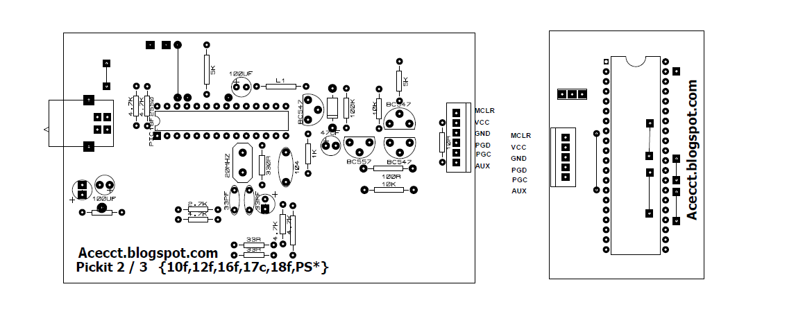


: BOTTOM PCB


: TOP PCB

3.2.5   PV PANEL MODEL

The simplest equivalent circuit of a solar cell is a current source in parallel with a diode as shown below. The current source represents the current generated by the PV cell due to the photons received by it, and is constant under constant sun irradiance and temperature. During darkness, the solar cell is not an active device; it works as a diode. It produces neither a current nor a voltage. However, if it is connected to an external supply (large voltage) it generates a saturation current or dark current. The key parameters for a PV cell are short circuit current (Isc or the current from the solar cell when the voltage across the cell is zero), open circuit voltage (Voc) and sun irradiance value. Usually these values are given by the manufacturer in the data sheet.

 PV CELL MODEL

Normally a single PV cell produces a rather small voltage that have less practical use. The
real PV panel always uses many cells to generate a large voltage. For example the Eco-tree
130W, PV module used for our project comprises of 36 cells to generate a large enough
voltage to charge a 12 volt battery. The data sheet for Eco-tree 130W, is given in Table below.

Parameter
Value
Maximum Power (Pmax)
130 W
Voltage At Pmax
17.6v
Current At Pmax
7.41a
Open-Circuit Voltage (Voc)
21.6V
Short-Circuit Current (Isc)
0.6A
Weight
12kg
Module Size
1480*680*35(Mm)


Featured post

PURE SINE WAVE INVERTER WITH LED AND LCD

The inverter PCB is easy to assemble by following the label of the components to be inserted. The choice of the voltage to be used to power ...