Tuesday, 2 February 2016

FINGER PRINT ACCESS CONTROL LOCK


FINGER PRINT ACCESS CONTROL USING FPM10A

In some situations, the use of keycards may not be suitable or sufficient. They can be lost, forgotten, given to someone else or manipulated. Some security environments require an exact verification of the user’s identity, which adds significantly to costs when done manually.
The most accurate and cost-efficient way to identify people is through biometric fingerprint system. A fingerprint cannot be stolen, which reduces security risk. It cannot be given to a colleague (by an employee), hence no more buddy punching. And a biometric fingerprint system costs a lot less than security guards.
     The featuring  mircontroller is the atmega326p with 32kb program memory size.

Fingerprint Recognition Module is : FPM10A which as the follwoing features:

Power supply voltage: DC 3.6~6.0V
Supply current: working current: <120mA
peak current: <140mA
The time of fingerprint image input: < 1 seconds
The window size: 14 x 18 mm
Profile: 256 bytes
Template file: 512 bytes
Storage capacity: 1000
False accept rate (FAR): < 0.001% (safety grade 3)
FRR (FRR): < 1% (safety grade 3)
The search time: < 1 seconds (1:500, mean)
Computer interface: UART (TTL logic level)
The communication baud rate (UART): (9600 x N) BPS where N=1 ~ 12 (the default value of N=6, namely 57600bps)
Working environment: temperature: -20°C to +50°C
Relative humidity: 40%RH to 85%RH (no treatment)
Storage conditions: temperature: -40°C to +85°C
Relative humidity: < 85%H (no treatment)
Dimensions (L * W * H):56 x 20 x 21.5mm
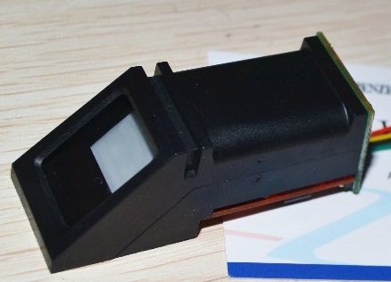


FPM10A  - Fingerprint Recognition Module


IST TEST WITH UNO AS SERIAL COMMUNICATOR


CIRCUIT DIAGRAM

COMPONENT SIDE 

 
 COPPER SIDE


PCB BOARD PRINTED


ASSEMBLING 1


 ASSEMBLING 2


FINISHED FINGER PRINT ACCESS CONTROL LOCK 


CODE:  // code written in c language

//ACE TECHNOLOGY '14
//FINGER PRINT ACCESS CONTROL
//ATMEGA328
//ACECCT.BLOGSPOT.COM

// set pin numbers:
const int ADD = 4;  // Funtion as both add and up key
const int  DELETE = 5; // Funtion as both delete and down key
const int  OK1 = 6; // ok KEY Funtion as both ok/ 1
const int DOWN0 = 7;  // down/0
int ID2 = 0;  

#include <Wire.h>
#include <Adafruit_Fingerprint.h>
#include <SoftwareSerial.h>
// include the library code:
#include <LiquidCrystal.h>

// initialize the library with the numbers of the interface pins
LiquidCrystal lcd(8, 9, 10, 11, 12, 13);

int getFingerprintIDez();
//uint8_t getFingerprintEnroll(int id);

// pin #2 is IN from sensor (GREEN wire)
// pin #3 is OUT from arduino  (YELLOW wire)
SoftwareSerial mySerial(2, 3);

Adafruit_Fingerprint finger = Adafruit_Fingerprint(&mySerial);

// CUSTOM LCD CHARACTERS  -------------------------
byte LOCK[8] = {
  0b00000,0b01110,0b10001,0b10001,0b11111,0b11011,0b11011,0b11111,};
byte UNLOCK[8] = {
  0b00000,0b01110,0b10000,0b10000,0b11111,0b11011,0b11011,0b11111,};
//--------------------------------------------------

int buzzerdelay = 150; // delay funtion 1
int buzzerdelay2 = 200; // delay funtion 2

void setup() {

  //PIN MODES DEFINATION AND RESETING ALL VARIBLES TO ZERO
  pinMode(A0, OUTPUT);  // LED
  pinMode(A1, OUTPUT);  // BUZZER
  pinMode(A2, OUTPUT);  // RELAY1
  pinMode(A3, OUTPUT);  // RELAY2

  pinMode(ADD, INPUT); // input for the ADD KEY
  pinMode(DELETE, INPUT); // input for the DEL KEY
  pinMode(OK1, INPUT); // input for the UP/1 KEY
  pinMode(DOWN0, INPUT); // input for the DOWN/0 KEY

  digitalWrite(A0, LOW);  // DEACTIVATED DOOR_LED>>>     OFF
  digitalWrite(A2, LOW);  // DEACTIVATED DOOR_RELAY1>>>  OFF
  digitalWrite(A3, LOW);  // DEACTIVATED DOOR_RELAY2>>>  OFF

  // initialize LCD and set up the number of columns and rows:
  lcd.begin(16, 2);

  //DEFINE CGRAM CREATED CHAR
  lcd.createChar(1, LOCK);
  lcd.createChar(2, UNLOCK);
  //---------------------------------------------------------------

  //---------------- QUICK INTRO -------------------

  lcd.setCursor(2,0);
  lcd.print("FINGER PRINT");
  lcd.setCursor(1,1);
  lcd.print("ACCESS CONTROL");
  delay (2500);
  //------------------------------------------------

  // set the data rate for the sensor serial port
  finger.begin(57600);

  // Cheak if fp is well connected
  if (finger.verifyPassword()) {
    delay(1000);
    lcd.setCursor(0,1);
    lcd.print("  Sensor Found  ");
    delay (2500);
    BUZZ();   
    delay(2500);

  }
  else {
    lcd.setCursor(0,1);
    lcd.print("Sensor not Found");
    delay (2500);
    while (1);
  }


}


//----- BUZZING FUNTION ---------------
void BUZZ()
{
  digitalWrite(A1, LOW);
  delay(buzzerdelay2);
  digitalWrite(A1, HIGH);
  delay(buzzerdelay);
  digitalWrite(A1, LOW);
  delay(buzzerdelay2);
}
//-------------------------------------------


//----- DELETING COMMAND ---------------
void DELETE2()
{
  uint8_t id = 0;
  int count = 0;
  lcd.clear();
  lcd.setCursor(0,1);
  lcd.print(" Deleting  Mode ");
  delay (2500);

  lcd.clear();
  lcd.setCursor(0,0);
  lcd.print(" Type in the ID ");
  lcd.setCursor(0,1);
  lcd.print("You want to Del.");
  delay (2800);

  lcd.clear();
  for (int count = 0; count < 2000; count++) {
    //+++++++++++++++++++++++++++++++++++++++++++++++++++++
    if ( digitalRead(ADD) == LOW)
    {
      id = ++ID2;
    }
    //-------------------------------------------------
    if ( digitalRead(DELETE) == LOW)
    {
      id = ID2--;
    }
    //-------------------------------------------------
    lcd.setCursor(0,1);      
    lcd.print("Deleting ID: ");
    lcd.print(ID2);
    delay (250);
    //-------------------------------------------------
    if ( digitalRead(OK1) == LOW) // OK  KEY IS PRESSED
    {
      count = 2000;
      BUZZ();
    }

  }
  delay (3500);
  if ( digitalRead(OK1) == LOW )
  {
    lcd.clear();   //    WRONG COMBINATION....... KEY
    lcd.setCursor(0,0);
    lcd.print("     WRONG      ");
    lcd.setCursor(0,1);
    lcd.print("  COMBINATION   ");
    delay (2500);
    count = 2000;
  }
}

//----- ADDING COMMAND ---------------
void ADD2()
{
  uint8_t id = 0;
  int count = 0;
  lcd.clear();
  lcd.setCursor(0,1);
  lcd.print("Enrollment  Mode");
  delay (2500);

  lcd.clear();
  lcd.setCursor(0,0);
  lcd.print("Enter the ID  #");
  lcd.setCursor(0,1);
  lcd.print("For this finger");
  delay (2500);

  lcd.clear();
  for (int count = 0; count < 2000; count++) {
    //+++++++++++++++++++++++++++++++++++++++++++++++++++++
    if ( digitalRead(ADD) == LOW)
    {
      id = ++ID2;
    }
    //-------------------------------------------------
    if ( digitalRead(DELETE) == LOW)
    {
      id = ID2--;
    }
    //-------------------------------------------------
    lcd.setCursor(0,1);      
    lcd.print("  Adding ID: ");
    lcd.print(ID2);
    delay (250);
    //-------------------------------------------------
    if ( digitalRead(OK1) == LOW) // OK  KEY IS PRESSED
    {
      count = 2000;
      BUZZ();
    }

  }
  delay (3500);
  if (digitalRead(OK1) == LOW )
  {
    lcd.clear();   //    WRONG COMBINATION....... KEY
    lcd.setCursor(0,0);
    lcd.print("     WRONG      ");
    lcd.setCursor(0,1);
    lcd.print("  COMBINATION   ");
    delay (2500);
    count = 2000;
  }
}

//_______________MAIN PROGRAM________________

void loop()  // Main loop
{
  uint8_t id = 0;
  lcd.clear();
  lcd.setCursor(0,0);
  lcd.print(" Place Your  ");
  lcd.write(byte(1));
  lcd.setCursor(0,1);
  lcd.print("Finger To Unlock");

  //+++++++++++++++++++++++++++++++++++++++++
  if ( digitalRead(ADD) == LOW)
  {
    uint8_t id = 0;
    ID2 = 0;
    delay(1000); // wait for 1 second
    digitalWrite(A0, HIGH);  // ACTIVATED DOOR_LED
    BUZZ();
    delay(1000); // wait for 0.5 seconds
    digitalWrite(A0, LOW);  // ACTIVATED DOOR_LED
    ADD2();

    getFingerprintEnroll(id);
  }

  //+++++++++++++++++++++++++++++++++++++++++++++++

  //+++++++++++++++++++++++++++++++++++++++++
  if ( digitalRead(DELETE) == LOW)
  {
    uint8_t id = 0;
    ID2 = 0;
    delay(1000); // wait for 1 second
    digitalWrite(A0, HIGH);  // ACTIVATED DOOR_LED
    BUZZ();
    delay(1000); // wait for 0.5 seconds
    digitalWrite(A0, LOW);  // ACTIVATED DOOR_LED
    DELETE2();

    deleteFingerprint();
  }

  //+++++++++++++++++++++++++++++++++++++++++++++++

  getFingerprintIDez(); 
  delay(30);  // get finger print id(S) 
}


//___________________ADD____________________________

int getFingerprintEnroll(int id) {
  uint8_t p = finger.getImage();
  while (p != FINGERPRINT_OK) {
    p = finger.getImage();
     
    if (p == FINGERPRINT_OK) {// GET IMAGE ON WINDOW
      lcd.clear();
      lcd.setCursor(0,1);
      lcd.print("  Image  taken  ");
      BUZZ();

    }
    if (p == FINGERPRINT_NOFINGER) {// GET IMAGE ON WINDOW
      lcd.clear();
      lcd.setCursor(0,0);
      lcd.print("   Place Your   ");
      lcd.setCursor(0,1);
      lcd.print("Finger To Enroll");
    }

  }

  p = finger.image2Tz(1);
  if (p == FINGERPRINT_OK) {//  convertion of image
    lcd.clear();
    lcd.setCursor(0,1);
    lcd.print("Image  converted");
    delay (1800);
    lcd.clear();
  }
  lcd.clear();
  lcd.setCursor(0,1);
  lcd.print(" Remove  finger ");
  delay (1800);
  lcd.clear();

  p = 0;
 
  while (p != FINGERPRINT_NOFINGER) {  //check if no finger on fingerprint
    p = finger.getImage();
  }
  p = -1;

  lcd.clear();
  lcd.setCursor(0,0);
  lcd.print(" Place the same ");
  lcd.setCursor(0,1);
  lcd.print("  finger again  ");
  delay (2000);

  while (p != FINGERPRINT_OK) {
    p = finger.getImage();
    if (p == FINGERPRINT_OK) {// GET IMAGE ON WINDOW
      lcd.clear();
      lcd.setCursor(0,1);
      lcd.print("  Image  taken  ");
      BUZZ();
      delay (2000);
      lcd.clear();
    }

    if (p == FINGERPRINT_NOFINGER) {// GET IMAGE ON WINDOW
      lcd.clear();
      lcd.setCursor(0,0);
      lcd.print("   Place Your   ");
      lcd.setCursor(0,1);
      lcd.print("Finger To Enroll");
    }
  }
   p = finger.image2Tz(2);
   if (p == FINGERPRINT_OK) {//  convertion of image
    lcd.clear();
    lcd.setCursor(0,1);
    lcd.print("Image  converted");
    delay (2200);
   }
  
  // convertion OK 
   p = finger.createModel();
  if (p == FINGERPRINT_OK) {
    lcd.clear();
    lcd.setCursor(0,1);
    lcd.print("Prints  matched!");
    delay (2500);
  }
  if (p == FINGERPRINT_ENROLLMISMATCH) {
    lcd.clear();  
    lcd.setCursor(0,0);
    lcd.print("  Fingerprints  ");
    lcd.setCursor(0,1);
    lcd.print(" did not match! ");
    delay (2500);
    return p;
  }
      lcd.clear();  
    lcd.setCursor(0,0);
    lcd.print("Ur  Fringerprint");
    lcd.setCursor(0,1);
    lcd.print(" ID Is:   ");
     lcd.print(ID2);
    delay (2500);
  p = finger.storeModel(ID2);
  if (p == FINGERPRINT_OK) {
    lcd.clear();
    lcd.setCursor(0,1);
    lcd.print(" Prints Stored! ");
    delay (3000);
  }
 
}

//___________________________________________________


//___________________DELETE____________________________
int deleteFingerprint( ) {
  uint8_t p = finger.deleteModel(ID2);
  p = finger.deleteModel(ID2);

  if (p == FINGERPRINT_OK) {// GET IMAGE ON WINDOW

    lcd.clear();
    lcd.setCursor(0,0);
    lcd.print("  Finger Print  ");
    lcd.setCursor(0,1);
    lcd.print("    Deleted!    ");
    delay (2800);
  }
}
//___________________________________________________


//Scan and search id image in database
int getFingerprintIDez() {
  uint8_t p = finger.getImage(); //=====

  if (p != FINGERPRINT_OK)  return -1;
  p = finger.image2Tz(); //=====
  if (p != FINGERPRINT_OK)  return -1;

  //--------- CONFIRMATION BUZZ ---------------- 
  digitalWrite(A1, HIGH);
  delay(buzzerdelay);
  digitalWrite(A1, LOW);
  delay(1500);    
  //--------------------------------------------

  p = finger.fingerFastSearch(); //=====

  if (p == FINGERPRINT_OK) {
    lcd.clear();
    lcd.setCursor(0,0);
    lcd.print("  Finger Print  ");
    lcd.setCursor(0,1);
    lcd.print("   Id Matched  ");
    delay (2000);
    lcd.clear();
    lcd.setCursor(0,1);
    lcd.print(" Your ID is: ");
    lcd.print(finger.fingerID);
    delay (2000);

    lcd.setCursor(0,0);
    lcd.print("Access Granted ");
    lcd.write(byte(2));
    lcd.setCursor(0,1);
    lcd.print("  DOOR  OPENED ");
    delay (1000);

    // Activate lock system
    delay(500);        //DELAY 0.5 Sec
    digitalWrite(A0, HIGH);  // ACTIVATED DOOR_LED
    digitalWrite(A2, HIGH);  // ACTIVATED DOOR_RELAY1>>>  ON
    digitalWrite(A3, LOW);  // DEACTIVATED DOOR_RELAY2>>>  OFF  
    delay (1500);
    digitalWrite(A0, HIGH);  // ACTIVATED DOOR_LED
    digitalWrite(A2, LOW);  // ACTIVATED DOOR_RELAY1>>>  ON
    digitalWrite(A3, LOW);  // DEACTIVATED DOOR_RELAY2>>>  OFF
    delay(500);        //DELAY 0.5Sec

    for (int count = 11; count >=0; count--) {
      lcd.clear();
      lcd.setCursor(0,0);
      lcd.print("Activating  lock"); // DISPLAY THE AMOUNT OF SECONDS
      lcd.setCursor(0,1);           // REMAINING
      lcd.print("In: ");
      lcd.print(count);
      lcd.print(" second(s)");
      delay(1000);        //DELAY 1 Sec
    }

    delay(500);        //DELAY 0.5 Secs
    digitalWrite(A0, HIGH);  // ACTIVATED DOOR_LED
    digitalWrite(A2, LOW);  // DEACTIVATED DOOR_RELAY1>>>  OFF
    digitalWrite(A3, HIGH);  // ACTIVATED DOOR_RELAY2>>>  ON
    delay(1500);

    //  DEFAULTING LOCK
    digitalWrite(A0, LOW);  // DEACTIVATED DOOR_LED>>>     OFF
    digitalWrite(A2, LOW);  // DEACTIVATED DOOR_RELAY1>>>  OFF
    digitalWrite(A3, LOW);  // DEACTIVATED DOOR_RELAY2>>>  OFF
    delay(2000); 
  }
  else if (p == FINGERPRINT_NOTFOUND) {
    lcd.clear();
    lcd.setCursor(0,0);
    lcd.print("  Finger Print  ");
    lcd.setCursor(0,1);
    lcd.print("  Not  Matched  ");
    delay (2000);
    return p;
  }

  return finger.fingerID;
}


Friday, 13 November 2015

PIC16F876A Based A.V.R ( VOLTAGE STABILIZER )

I have be thinking about a pic microcontroler based voltage regulator for about 3 years now; last week i install a 2.5kva 36V inverter for a consumer of mine... 3 days later he called me that the inverter is not charging the battery well... so i ask him to call me and check the input voltage on the lcd screen when ever their is a mains supply (NEPA).... so he called  confirming that the input voltage was 108volt; we had to design a  2kva automatic voltage regulator from 80V - 260V...

Features:
Low voltage protection
High voltage protection
Delay function
Calibration mode
Delay indicator
High/low voltage indicator


4 Relays voltage stabilizer

 ON 187V INPUT TEST ON PROTEUS

 ON 218V INPUT TEST ON PROTEUS 

 ON 262V INPUT TEST ON PROTEUS WITH HIGH VOLT GUIDE 


RELAY CONFIGURATION

TRANSFORMER CONFIGURATION


A

 
B


Repair of 2kva AVR


Old board


New board


TEST1


READY


Monday, 3 August 2015

GSM/GPS VEHICLE GEOGRAPHICAL TRACKER


The project is based on a Gsm/Gps/Gprs. Its main function is to detect a illegal entry and communicate its own geographical position using, on the choice, the cellular phone reference system or the GPS. I use the recent product by SIMCOM - SIM908 which operate on 5 - 12 volt  dc supply, which makes it work on wide-range dc power supply...  Well i still cant believe that i  can burn a code of 21kb  into program memory chip of 14kb (pic16f876a), but, it works all good.... 
maybe one of this days am gonna write a code of 30kb on this mircontroller chip, just wanna confirm the max. program memory size....  
 The featuring  mircontroller chip is the pic16f876a, the reason i keep using this chip is because it cost less than $2 and I guess is available in all country... 


1st TEST VIDEO

The GPS Tracker is a small gadget that will record exactly where your vehicle, boat or aeroplane has travelled over time. It is intended to be wired into the ignition of your vehicle and then forgotten.
It will record your travels in Google Earth format, GPS Exchange format or as raw NMEA data and using software such as Google Earth you can then see your trips mapped onto the surface of the earth with a resolution of a few meters. Below are my experimental pics, pcb layout, and code....


PROTEUS SIMULATION 


SIM908 CONNECTION 1


SIM908 CONNECTION 2

PCB MAKING 1

PCB MAKING 2


PCB AND COMPONENT FIXING

PC GPS SERIAL BOARD QUICK TEST


FIRST TEST ON GET GPS LOCATION WITH SMS COMMAND


COMPLETE PCB LAYOUT AND CODE: http://1drv.ms/1Lof3e1

Code written in picbasic pro
'GSM AND GPS CONTROLLER
'PROGRAMMER : AYOMIDE
'USER: OPEYEMI
'ACECCT.BLOGSPOT.COM
'PIC16F876A
'2015

 DEFINE OSC 4
     include "modedefs.bas"

' Define ADCIN parameters
Define ADC_BITS     10    ' Set number of bits in result
Define ADC_CLOCK    3     ' Set clock source (3=rc)
Define ADC_SAMPLEUS 50    ' Set sampling time in uS

'-------------[PORT INITIALIZATION]-----------------
      ' 76543210
TRISA = %11111111
ADCON1 = 7
PORTB = 000000  'reset portB resigters to zero
TRISB = 000000  'Setting portB as output port
PORTC = 000000  'reset portC resigters to zero
TRISC = %10000000

'--------------[LCD DEFINES]----------------------
DEFINE LCD_DREG PORTB ' LCD Data bits on PORTB
DEFINE LCD_DBIT 4 ' PORTB starting address
DEFINE LCD_RSREG PORTB ' LCD RS bit on PORTB
DEFINE LCD_RSBIT 2 ' LCD RS bit address
DEFINE LCD_EREG PORTB ' LCD E bit on PORTB
DEFINE LCD_EBIT 3 ' LCD E bit address
DEFINE LCD_BITS 4 ' LCD in 4-bit mode
DEFINE LCD_LINES 2  ' DEFINE LCD ROW AS 2

'VARIABLE ------------------------------
LCD_MOVE VAR WORD ' LCD AMINATION
AT_TEST VAR WORD : AT_TEST = 0
OWNER VAR WORD
SENDER VAR BYTE[25] : SENDER = 0
NET2 VAR WORD
A0 VAR WORD : A0 = 0
BUFF160        VAR BIT[160]
ENCODER90 VAR BYTE[90]
LAT20 VAR BYTE[20]
LONG20 VAR BYTE[20]
ENCODER10 VAR BYTE[10]
A2 VAR WORD : A2 = 0
KEY VAR PORTB.0
B0 VAR WORD
LOCATE VAR WORD : LOCATE = 0

'--------- ASCII ---------------
ENTER con 13
CTRLZ CON 26

' ------- COMMUNICATION PORT --------------
REMOTE_RX VAR PORTC.0
GSM_TX VAR PORTC.6
GSM_RX VAR PORTC.7

' ----------- PORT ALIASES -----------------
OWNER_SW VAR PORTA.5
BOOT VAR PORTA.1
DOOR VAR PORTA.2
BONNET VAR PORTA.3
RELAY_RX VAR PORTA.4

SECURED_LED VAR PORTC.0
ENGINE_LED VAR PORTC.1
DOOR_LED VAR PORTC.2

BUZZER VAR PORTC.3
ENGINE_RELAY VAR PORTB.0
DOOR_RELAY VAR PORTB.1


'---------[LCD INITIALIZATION]-----------
LCDOUT $FE,1 ' CLEAR SCREEN
LCDOUT $FE,2
PAUSE 500          ' Wait .5 second for lcd to ready

ON_MODULE:  ' ACTIVATE GSM/GPRS/GPS MODULE
low BUZZER: LOW RELAY_RX: LOW ENGINE_RELAY: LOW DOOR_RELAY
HIGH ENGINE_LED : HIGH DOOR_LED : HIGH SECURED_LED : PAUSE 1000
LOW ENGINE_LED : LOW DOOR_LED : LOW SECURED_LED
      PAUSE 10: LOW PORTC.5: PAUSE 1000
      HIGH PORTC.5: PAUSE 500
   high BUZZER : PAUSE 800: low BUZZER: PAUSE 200
   LCDOUT "AJAYI OMOYEMI A."  : LCDOUT $FE, $C0
LCDOUT "  EEE/11/5048   "
PAUSE 2500
LCDOUT $FE,1 ' CLEAR SCREEN  
CHECK_GSM:
CLEAR          ' CLEAR ALL VARIABLE

'++++++++++++++++++++++++++++++++++++++++++++++++++++++++++
for AT_TEST = 0 to 3
SEROUT2 GSM_TX,84,["AT",$0D,$0A]
     LCDOUT $FE, $C0 : LCDOUT " Initialize !!! "
       lcdout $fe,$8
        pause 500
          lcdout $fe,$c
            pause 500
next AT_TEST

PAUSE 300  
SEROUT2 GSM_TX,84,["AT+CMGF=1",ENTER] : PAUSE 300
   SEROUT2 GSM_TX,84,["AT+CMEE=1",ENTER] : PAUSE 300
     
LCDOUT $FE,1 ' CLEAR SCREEN
FOR NET2 = 0 TO 2      ' GET NETWORK STATUS
PAUSE 100 : LCDOUT "SEARCHING SIM908"
   SEROUT2 GSM_TX,84,["AT+CSQ",ENTER]
     SERIN2 GSM_RX,84,3000,CHECK_GSM,[WAIT("+CSQ: "), STR ENCODER90\6] : PAUSE 2
         LCDOUT $FE, $C0 : LCDOUT "  CSQ:    ", STR ENCODER90\6  : PAUSE 1500
NEXT NET2

PAUSE 2
SEROUT2 GSM_TX,84,["AT+CSQ",ENTER]
  SERIN2 GSM_RX,84,3000,GSM_CHECK_ERR,[WAIT("OK")]  : pause 100
      LCDOUT $FE, $C0 : LCDOUT "SIM908 CONNECTED" : PAUSE 2500
         HIGH BUZZER :PAUSE 500 :LOW BUZZER  :PAUSE 200
            HIGH BUZZER :PAUSE 500 :LOW BUZZER  :PAUSE 2
GOTO SEND_OKGSM

GSM_CHECK_ERR:
LCDOUT $FE, $C0 : LCDOUT " NOT  CONNECTED "
PAUSE 1500

'*****************************************************************
SMS_SETUP:
PAUSE 500
SEROUT2  GSM_TX,84,["AT+CMGF=1",ENTER]    ' SW TO SMS MODE
PAUSE 500
SEROUT2 GSM_TX,84,["AT+CMGS=",34,"+2348100581270",34,ENTER]
PAUSE 500
RETURN

SEND_SMS:
PAUSE 300
  SEROUT2 GSM_TX,84,[CTRLZ]
     SEROUT2 GSM_TX,84,[26]
        PAUSE 5000
LCDOUT $FE,1 ' CLEAR SCREEN
   LCDOUT $FE, $C0 : LCDOUT "  MESSAGE SENT "
   HIGH BUZZER :PAUSE 500 :LOW BUZZER  :PAUSE 3000
   LCDOUT $FE,1 ' CLEAR SCREEN
  
      RETURN
'******************************************************************

SEND_OKGSM:
GOSUB SMS_SETUP
SEROUT2 GSM_TX,84,["SIM908 - GSM/GPRS/GPS CONNECTED AND OK, "," NETWORK CSQ: ",STR ENCODER90\6,_
" [ VEHICLE SECURED ]",ENTER]  :PAUSE 500
   GOSUB SEND_SMS
      PAUSE 1000

MAIN_PROGRAM:
LCDOUT $FE,1 ' CLEAR SCREEN
   LCDOUT "SIM908 CONNECTED"
      LCDOUT $FE, $C0 :LCDOUT "VEHICLE  SECURED"
      HIGH SECURED_LED :PAUSE 500 :LOW SECURED_LED 
         PAUSE 700

IF BOOT = 0 OR DOOR = 0 OR BONNET = 0 THEN  ' CHECK DOOR
  HIGH BUZZER :PAUSE 500 :LOW BUZZER  :PAUSE 200
    HIGH BUZZER :PAUSE 500 :LOW BUZZER  :PAUSE 200
    HIGH BUZZER :PAUSE 500 :LOW BUZZER  :PAUSE 2
 SEROUT2  GSM_TX,84,["AT+CMGD= 1",ENTER]  
      LCDOUT $FE, $C0 :LCDOUT " VEHICLE OPENED "
        PAUSE 2000
GOTO CHECK_OWNER
ENDIF
PAUSE 2000
GOTO MAIN_PROGRAM


CHECK_OWNER:
LCDOUT $FE,1 ' CLEAR SCREEN
PAUSE 2
 FOR OWNER = 1 TO 15
   LCDOUT "  VERIFY OWNER  "
     LCDOUT $FE, $C0 :LCDOUT " IN 15 SECOND(S)"
       PAUSE 1000
        IF OWNER_SW = 0 THEN MAIN_PROGRAM
 NEXT OWNER
 IF OWNER = 15 THEN GOTO SMS_OWNER
 SMS_OWNER:
SEROUT2 GSM_TX,84,["AT+CMGD=1",ENTER] : PAUSE 1000  ' DELETE ALL INBOX
GOSUB SMS_SETUP
SEROUT2 GSM_TX,84,["AN INTRUDER DETECTED, REPLY (CMD:ACIVATE_ LOCK (OR) UNLOCK, ALARM (OR)SILENT, GET_LOCATION, OWNER",ENTER]  :PAUSE 500
   GOSUB SEND_SMS
     PAUSE 1000
  CLEAR
DECODE_SMS:
  LCDOUT $FE,1 ' CLEAR SCREEN
PAUSE 100
LCDOUT "WAITING FOR  SMS": PAUSE 500
SEROUT2  GSM_TX,84,["AT+CMGR= 1",ENTER]    ' READ INBOX 1
'SERIN2  GSM_RX,84,3000,DECODE_SMS,[WAIT("+CMGR:"),SKIP 0, STR ENCODER90\20] : PAUSE 50
SERIN2  GSM_RX,84,1500,DECODE_SMS,[WAIT(47),SKIP 14, STR ENCODER90\24] : PAUSE 50
LCDOUT $FE, $C0
LCDOUT "SMS 1: ", STR ENCODER90(19)
    'for B0=1 to 108    'MOVE LEFT
     ' lcdout $fe,$1e
        pause 3000
    'next B0
   
if (ENCODER90(19)="L") THEN      ' ACTIVATE LOCK
HIGH DOOR_RELAY  : HIGH DOOR_LED
HIGH ENGINE_RELAY : HIGH ENGINE_LED: PAUSE 5
GOSUB DELETE_SMS
ENDIF
if (ENCODER90(19)="U") THEN     ' ACTIVATE UNLOCK
LOW DOOR_RELAY  : LOW DOOR_LED
LOW ENGINE_RELAY : LOW ENGINE_LED: PAUSE 5
GOSUB DELETE_SMS
ENDIF
if (ENCODER90(19)="A") THEN    ' ACTIVATE ALARM
HIGH BUZZER : PAUSE 5
GOSUB DELETE_SMS
ENDIF
if (ENCODER90(19)="S") THEN      ' ACTIVATE SILENT
LOW BUZZER : PAUSE 5   
GOSUB DELETE_SMS
ENDIF
if (ENCODER90(19)="G") THEN     ' ACTIVATE GET LOCATION
LOW BUZZER : PAUSE 5
gosub  GET_LOCATION  
GOSUB DELETE_SMS
ENDIF
if (ENCODER90(19)="O") THEN    ' ACTIVATE OWNER
LOW BUZZER
LOW DOOR_RELAY  : LOW DOOR_LED
LOW ENGINE_RELAY : LOW ENGINE_LED: PAUSE 5 
GOSUB DELETE_SMS
LCDOUT $FE,1 ' CLEAR SCREEN
LCDOUT "VEHICLE  SECURED"  : LCDOUT $FE, $C0
LCDOUT " OWNER VERIFIED "
PAUSE 10000
GOTO MAIN_PROGRAM
ENDIF
GOTO DECODE_SMS

DELETE_SMS:
 SEROUT2  GSM_TX,84,["AT+CMGD= 1",ENTER]
 PAUSE 1
 RETURN

 GET_LOCATION:
CLEAR
LCDOUT $FE,1 ' CLEAR SCREEN
PAUSE 50     
SEROUT2  GSM_TX,84,["AT+CGPSPWR=1",ENTER]    ' POWER ON THE GPS MODULE
PAUSE 500
SEROUT2  GSM_TX,84,["AT+CGPSRST=1",ENTER]    ' POWER ON THE GPS MODULE
PAUSE 500
SEROUT2  GSM_TX,84,["AT+CGPSIPR=9600",ENTER]    ' POWER ON THE GPS MODULE
PAUSE 500

LOCATION:
for LOCATE = 0 TO 2
SEROUT2  GSM_TX,84,["=AT+CGPSINF=32",ENTER]    ' get location
'HSERIN 2000,SETUP,[SKIP 5,WAIT (10),STR BUFF\20\13]
'SERIN2  GSM_RX,84,[WAIT("+CMGR: "),SKIP 45, STR ENCODER90\20] : PAUSE 200
SERIN2  GSM_RX,84, 1000, LOCATION,[WAIT("A,"),STR LAT20\12] : PAUSE 200
PAUSE 500
SEROUT2  GSM_TX,84,["AT+CGPSINF=32",ENTER]    ' get location
SERIN2  GSM_RX,84,[WAIT("N,"),SKIP 0, STR LONG20\12] : PAUSE 200
LCDOUT $FE,1 ' CLEAR SCREEN

PAUSE 200
LCDOUT $FE, $C0
LCDOUT "DOWNLOADING....."
PAUSE 1500
NEXT LOCATE
'------- SEND LOCATION TO MOBILE ------------------------
GOSUB SMS_SETUP
SEROUT2 GSM_TX,84,[" CURRENT VEHICLE LOCATION :::  LAT :", STR LAT20\12,"   ","LON: ", STR LONG20\12  , ENTER] 
PAUSE 500

'SEROUT2 GSM_TX,84,["SIM908 - GSM/GPRS/GPS CONNECTED AND OK, "," NETWORK CSQ: ",STR ENCODER90\6,_
'" [ VEHICLE SECURED ]",ENTER]  :PAUSE 500
   GOSUB SEND_SMS
      PAUSE 1000
RETURN

end


If you have any question, feel free to comment on this post and ask me any question.... acecct.18f4550@gmail.com OR call me on :  +2348123206299

Thursday, 25 June 2015

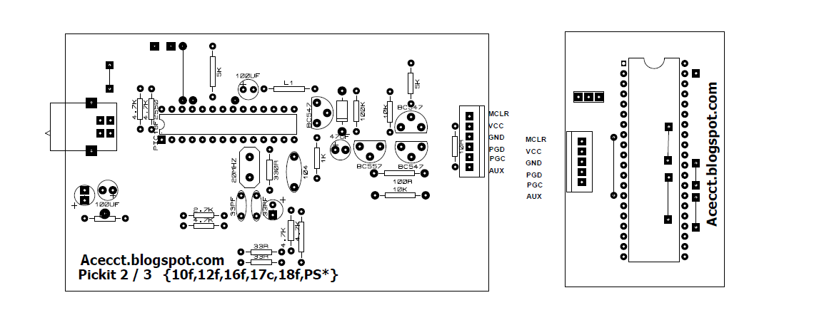
PICKIT 2 CLONE PROGRAMMER

PICKIT 2 CLONE PROGRAMMER

PROJECT DESCRIPTION:

This is my PICkit 2 clone design. Its based on a simplified version of the Microchip PICkit 2 schematic and only supports 5v parts. It works with all the Microchip software including MPLAB, MPLABX,the PICkit 2 GUI Programming software and the PICkit 2 command line software.


FIG1: CIRCUIT DIAGRAM


FIG2: 3D PREVIEW

FIG3: PCB  VIEW1


FIG4: PCB  VIEW2


FIG5: PCB  VIEW3


FIG6: TESTING1


FIG6: 28 PIN uC configration


FIG6: 18 PIN uC configration


FIG6: 8 PIN uC configration 


FIG6: 8 NEW PICKIT2 WITH DSP SOCKET


To purchase PICKIT 2 CLONE PROGRAMMER (empty & complete) 
Lagos (nigeria): Call- 09020322481
Akure (nigeria): Call- 08123206299
Email :  acecct.18f4550@gmail.com 

 If you have any question, feel free to comment on this post.... acecct.18f4550@gmail.com OR whatsapp me on :  +2348123206299

PICKIT 2 CLONE PROGRAMMER COMPLETE FILE:  https://www.datafilehost.com/d/b06ac5ef

Featured post

PURE SINE WAVE INVERTER WITH LED AND LCD

The inverter PCB is easy to assemble by following the label of the components to be inserted. The choice of the voltage to be used to power ...