proudly NIGERIA......
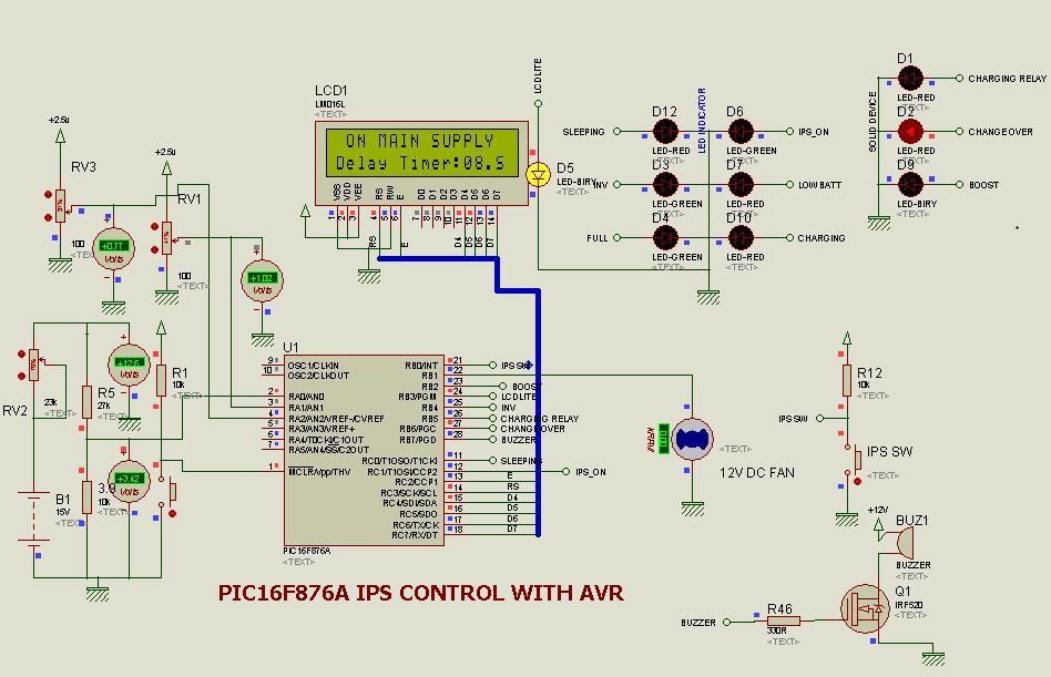
The featuring M.C.U is the Microchip PIC16F876A
FEATURES OF THE ABOVE SCHEMATIC ARE STATED BELOW :
INVERTER PROTECTION : LOW-BATTERY SHUTDOWN
: OVER LOAD SHUTDOWN INPUT
: O/P SHORT CCT SHUT-DOWN INPUT
: HIGH TEMPERATURE SHUT-DOWN INPUT
: LOW-BATTERY : BEEP START AT 11 V
:INVERTER SHUT DOWN AT 10.5 V
:10 SEC DELAY BEFORE CHARGING
: AUTOMATIC VOLTAGE REGULATOR
[INPUT: 180 V - 240 V]
[OUTPUT: 211 V - 232 V]
INVERTER MONITOR : 16*2 LCD DISPLAY
: ERROR LED
: BUZZER

: OLD DESIGN 1

:OLD DESIGN 2

: OLD DESIGN 3

: NEW DESIGN 1

: NEW DESIGN 2

: NEW DESIGN 3

: FINISHING 1

: FINISHING 2

: FINISHING 3

: FINISHING 4

PROTEUS SIMULATION 1

PROTEUS SIMULATION 2

PROTEUS SIMULATION 3

PROTEUS SIMULATION 4

PROTEUS SIMULATION 5

PROTEUS SIMULATION 6

PCB DESIGN TOP VIEW

Complete ips board
DOWNLOAD LINKS:
1) ISIS, PCB AND CODE: https://onedrive.live.com/redir?resid=4461D551EDBCA377!469&authkey=!AP5XoGGx2xSMiKQ&ithint=folder%2chex
2) SHORT LINK: http://1drv.ms/1EXaDeq
If you have any question, feel free to comment on this post.... acecct.18f4550@gmail.com or (234)8123206299
Reference documents:
PIC16F876A datasheet: ww1.microchip.com/downloads/en/devicedoc/39582b.pdf


Good work. Does this one have lcd display also? Can you please upload the schematic diagrams. Thanks.
ReplyDeleteGood work bros, please upload the schematic diagrams and that of the power mosfet i.e how you connect your mosfet. Thanks.
ReplyDeleteCan have your phone numba brother
ReplyDeleteplease inverter degine pcb mosfat power complete layout send mh1877196@gmail.com
ReplyDeleteThank you very much for this circuit, but the code is incomplete there are some errors in the code that disgracing the circle.
ReplyDelete1. You can not turn on or off ips when there MAIN SUPPLY
2. In case ips in playback mode The MAIN SUPPLY exist
When the outage will not be switching to the inverter only if it reaches the reading when I / Put VOLT This works to slow the switch
Ayo am proud of you may God bless and empower u
ReplyDelete
ReplyDeletehi dear its very first-class and very helpful submit for those who are new and thinking to begin a weblog site.Your posts are very helpful and creative mitsubishi